| The Display | ||
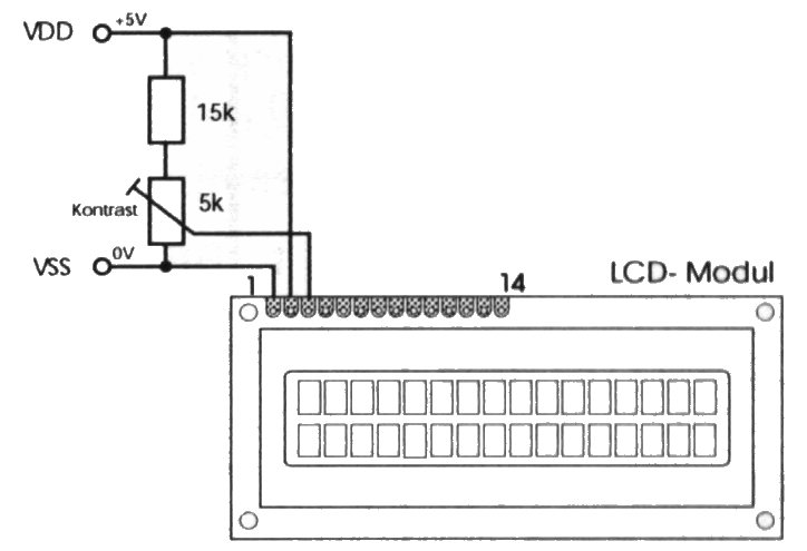
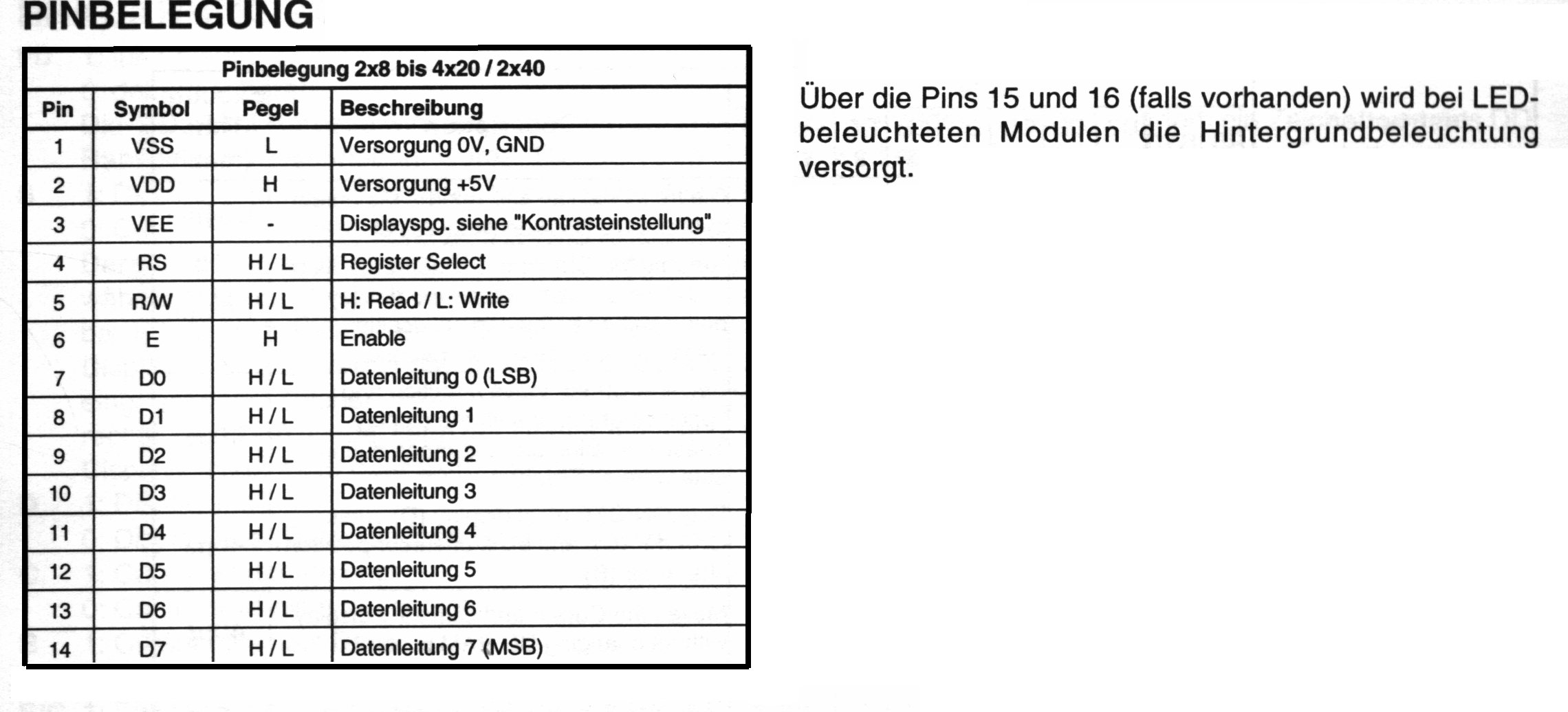
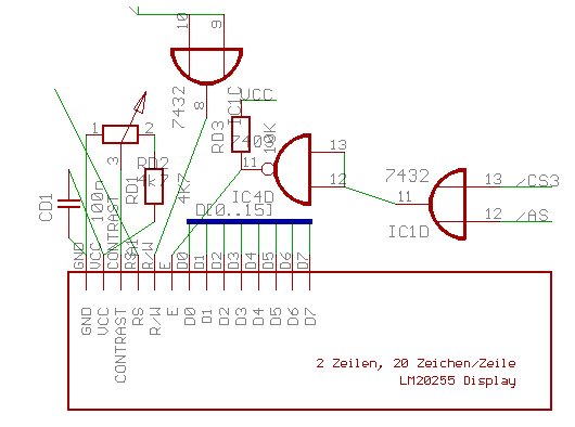 I use a standard 20x2 chars/line character display from hitachi with backlight. Especially the backlight was really importance since (at least me...) wants to know the title even if its dark ;-)The display. Pin 1 must be connected to GND, pin 2 with VCC (5V) - no magic. Pin 3 is used for contrast regulation hence must be connected to a variable resistor. Note: at least the model I bought changed its contrast after a short while (when it was heating up). So, don't close the case to early... Pin 4 selects one of the two registers of the HD44780 controller chip. Information about this chip (and all the other ICs I used from hitachi) can be found on their website. Even a databook CD can be ordered there (for free!). This pin (RS) must be connected to A1. This trick saves an extra decoderchip since otherwise one would have to difference between even and odd access to the register set. The hitachi controller has a 16 bit databus and uses either the lower or the upper 8 bits for access to 8-bit areas depending on the lowest address bit A0. So, for register 0 we would have to use the upper 8 bit to the display databus, resp. for register 1 we need to connect the lower 8 bits to the display databus. If we use A1 as basis for all registers, all registers are on a even boudary and always the upper 8 bits of the databus carry the information for the display whereas we may safely ignore the lower portion of the databus. Display pinout. Pin 5 signals read/write access to the display controller. Reading is important since this is used by the controller that it cannot execute another command as long as its status bit remains true, at least, the execution time of the next command will rise if the program did not wait for the current command to complete (this is what the databook says.). Well, nevertheless I did not use the statusbit. The program just makes sure that it does not issue the next command as long as the current command may be executed. Execution times can be found in the datasheet. This pin is connected to RD. Pin 6 "Enable" is connected to the display's chip select line. This is CS3 (not to be mixed with /CS3 from the ide interface!!). For the chip expects the signal beeing active high, the signal is inverted. In addition, AS has to be taken into account since the CS as generated by the hitachi microcontroller indicates access to the segment before the addresslines are valid!
|